John Kornegay

Recent Posts

Fusion or Mechanical: Which Is the Best Splicing Method?

Posted by John Kornegay on Wed, Feb 2, 2022 @ 09:02 AM

The act of joining two individual lengths of optical fiber to create a secure connection is called splicing. There are currently two common splicing methods that can be utilized - fusion splicing and mechanical splicing. While both processes share similar initial steps, the differ substantially thereafter in terms of the approach and necessary materials, while producing different results.

With this being the case, how might one choose which path to take? Is one method considered better than the other? In this brief article, we take a closer look at both the fusion and mechanical splicing methods to provide some clarity on the subject. At the conclusion, you should have better idea about how each method works, the benefits and drawbacks of each, and which uses cases or applications are more suited to one or the other.

 
Figure 1: Fusion Splicer machine close-up

Defining Mechanical & Fusion Splicing

The ultimate goal of cable splicing is to create a secure connection between two or more sections of fiber in a way that allows the optical signal to pass through with minimal loss. As we mentioned already, both mechanical and fusion splicing achieve this goal, but they do so in very different ways.

Fusion Splicing

Fusion splicing involves heating the ends of each fiber that are being joined and fusing them together permanently. Because this process requires near-perfect alignment of the fibers and their respective cores, along with fusing the glass together in a precise manner, this is accomplished using a fusion splicer device. The device effectively aligns the two fiber ends, melts the glass via an electric arc, then fuses them together. Because of the resulting splice point in the length of fiber, either a heat-shrinkable protective splice sleeve or a coating material is typically placed over the splice point to give the splice more strength and durability.

Mechanical Splicing

The primary way that mechanical splicing differs from fusion splicing is that it is a manual process that does not permanently fuse or join the fibers together, instead it locks and aligns the fiber ends together with a screw mechanism in a splice case. This method requires no heat or electricity and is performed manually by a technician using the required tools and components.

Fusion Splicing Steps - A Quick Overview

For both fusion and mechanical splicing techniques, there are four distinct steps to the process. The first two steps for each are virtually identical which are covered in this section, but the final two are where the differences come into play.

Fusion Splicing and Mechanical Splicing Step 1 - Fiber / Cable Preparation

To prepare the end of a fiber cable for splicing, a few inches of the protective jacketing, buffer tubing, and coating must be stripped away in order to access the bare glass fiber. After using a handheld stripping tool to remove these layers, the bare fiber is now accessible, which should then be cleaned quickly with an alcoholic wipe to remove any dirt or dust.

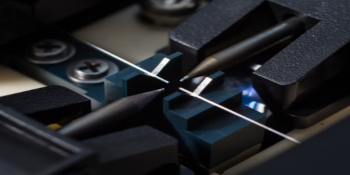
Fusion Splicing and Mechanical Splicing Step 2 - Cleaving

Once the bare fiber is prepared, the next step involves cleaving the end fiber, which shouldn’t be confused with cutting. Cleaving is when the fiber is lightly scored with a sharp blade and then flexed until it naturally breaks. To create an ideal connection point for a fusion or a mechanical splice, a clean and smooth cleave that is perpendicular to the fiber is absolutely necessary. The example image below shows examples of poor cleaves on the left and good cleaves on the right:

Read More

Topics: optical fiber, mechanical splice, fusion splice

The Importance of Simulating PON Networks Before Deployment

Posted by John Kornegay on Fri, Jun 21, 2019 @ 12:06 PM

The fact that fiber optics are used in the transmission of light-signal data is widely known, as is the fact that separated ways are required to allow those signals to arrive at their intended destination. Typically speaking, there are two types of network that are employed to achieve this goal:

Read More

Topics: PON

Fiber Optic Network and Latency Simulator Saves Significant Rack Space

Posted by John Kornegay on Fri, Apr 12, 2019 @ 10:04 AM

The versatile Fiber Lab 750 from M2 Optics offers multiple lengths of optical fiber in just 3RU, saving 50% or more rack space for engineers.

Read More

Topics: latency, optical time delays

High-Density Optical Time Delay Platform for Fiber Optic Networks

Posted by John Kornegay on Fri, Mar 29, 2019 @ 17:03 PM

The customizable Fiber Lab 250HD from M2 Optics provides a versatile solution for communications service providers, test labs, and research institutions.

Read More

Topics: optical time delays

Eliminate the “Dead Zone” With an OTDR Launch Box

Posted by John Kornegay on Wed, Jan 23, 2019 @ 16:01 PM
The Optical Time Domain Reflectometer (OTDR) is a vital tool for fiber optic testing that can analyze the performance of fiber optic cabling through the use backscattering technologies, as well as identifying and locating connectors, splices, and breaks in fiber optic networks.

However, there is an unwanted phenomenon known as ‘dead zone’ that occurs when using an OTDR, which can cause improper readings if the right steps aren’t taken. This dead zone limitation can be avoided through the use of an OTDR Launch Box, which is what we review in more detail here.

The Launch Box Basics

The launch box, which is also known in the industry as a launch fiber, pulse suppressor, dead zone box or fiber ring, is a device that helps to eliminate the dead zone issue during fiber optic testing significantly. The dead zone is something that occurs when the pulse width changes and causes a high degree of reflection that can cover an area several hundred meters from where the OTDR is located. This results in the OTDR device not being able to detect events or issues in that area.

A term launch box is a box that contains a long spool of fiber that is placed in between the fiber being tested and the OTDR. This provides extra fiber on which the dead zone can occur. This enables the OTDR to now detect events at the beginning of the fiber being tested.

Using Your Launch Box

Launch boxes come in various shapes and sizes. However, all tend to have a robust outer casing to make them more durable. Each end of the fiber is terminated, with one to be attached to the OTDR and the other to the fiber being tested. Once connected to the relevant ports, the test can be run accordingly.

While using an OTDR box is a relatively simple process, you must be sure that it contains a sufficient length of fiber to take account of the entire dead zone or you still won’t achieve a proper reading on your trace and could miss events. Choosing the right OTDR launch box is important, as they can be customized to the specific application or device.


M2 Optics OTDR Sidekick Launch Box Solution


Choosing the Right One

When choosing the right OTDR launch box for your needs, you should approach it in the same way as you would choose a fiber patch cable. Box styles along with features such as connector type, fiber type, and fiber length should all be determined. Furthermore, some launch boxes are available with bulkhead adapters while others provide directly terminated fiber ends.

As mentioned before, a dead zone can cover several hundred meters, so your launch box spool should be long enough to cater for this. It is important to make sure you choose one that suits the job, and your OTDR user manual can provide guidance regarding the expected dead zones.

Learn More


If you would like to learn more about anything else relating to packaged optical fiber solutions, network simulation, and latency/time delays, please get in touch with us at M2 Optics by calling us on 919-342-5619 or, visit our website www.m2optics.com.


Contact M2 Optics For Your FREE Fiber Consultation!

Since 2001, M2 Optics has been an established manufacturer and innovator of professional optical fiber platforms for fiber network simulation, latency / optical time delay, training, and demonstration applications. Our customer base includes many of the world's most recognized communications service providers, equipment manufacturers, data centers, web service providers, financial institutions, research institutions, and government agencies.
Read More

Topics: otdr

Reduce Truck Rolls With Fiber Monitoring

Posted by John Kornegay on Wed, Dec 19, 2018 @ 11:12 AM

When supporting high-usage services, there is always a chance for service disruption, which directly impacts the customers. When service outages arise, service providers and businesses are in a reactionary position while attempting to locate the system failure. Depending on the structure of the troubleshooting protocol for a service provider or business, there can be many steps taken before a technician is deployed. Once the technician is deployed, there still is a chance that challenged can arise for them locating the exact fault.

Read More

Topics: fiber monitoring

Benefits of Using Fiber Optic Attenuators with Doped Fiber

Posted by John Kornegay on Thu, Oct 18, 2018 @ 12:10 PM

Fiber optic attenuators are used in networking applications where an optical signal is too strong and needs to be reduced. There are many applications where this arises, such as needing to equalize the channel strength in a multi-wavelength system or reducing the signal level to meet the input specifications of an optical receiver. In both scenarios, reducing the optical signal strength is necessary or else system performance issues may arise.

Read More

Topics: optical fiber

Four Benefits of Protecting Your Optical Fiber In A Test Environment

Posted by John Kornegay on Mon, Sep 10, 2018 @ 15:09 PM

If you are in the line of work where you are simulating networks using optical fiber, it is safe to assume that you have a few spools of bare fiber sitting in your test environment. The importance of ensuring your fiber-based network devices will work as envisioned before deployment in the field is vital. However, running simulations using unprotected or unsecured spools fiber can prevent you from producing the maximum results due to challenges that can arise.

Read More

Topics: fiber optic testing

Sources of Latency in a Financial Communications Network

Posted by John Kornegay on Tue, Aug 14, 2018 @ 10:08 AM

The world’s financial communication networks are a paradigm of the modern world, and they operate at very high speeds through necessity, often using fiber optic technology. So fine are the lines between success and failure in today’s trading environment that just tiny fractions of seconds do matter. When financial institutions trade via these networks, shaving microseconds off network latency can result in a significant competitive advantage and millions of dollars annually. To reduce latency, one must understand the factors that can cause latency.

Read More

Topics: latency

Why Is Latency So Important In Financial Networks?

Posted by John Kornegay on Tue, Jul 10, 2018 @ 12:07 PM

When talking about computers, latency is a word used to describe how long after you input a command that the results of that command are displayed on the screen. In technical terms, it’s the measured delay involved getting a datagram or packet from one hardware location to another and so obviously, the lower the latency, the better performing the device or network is.

Read More

Topics: latency