
Topics: fiber optic testing, optical fiber, fiber lab
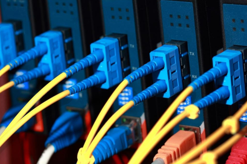
The use of fiber optic cables for communications dates back to the 1950s when some of the first demonstrations of the world’s earliest transmission systems occurred. Since then, continuous innovation of optical fiber has significantly improved the performance characteristics to a level that now fiber optic cables serve as the backbone for global communications systems.
Topics: fiber optic training, fiber monitoring
From the planet's largest machine to the latest quantum encryption, optical fibers play a key role in technology innovation as they enable phenomenally high data rates. Installed at the depths of the oceans, throughout cities, and in the most hostile environments on earth, optical fibers serve as the backbone for connecting global communications systems and delivering massive amounts of data every day.
Topics: fiber optic testing, network simulation, latency
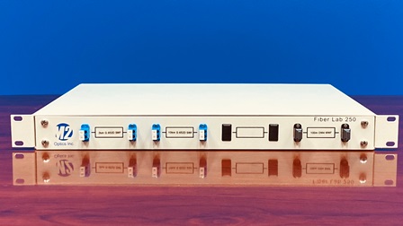
In addition to serving as an important workspace, today’s fiber optic testing labs often host visitors like potential customers or technology partners for demonstrations. As a result, the appearance of the lab is important and can influence a visitor’s perception of the company. A crowded or disorganized lab is not only challenging for engineers to use, but it can also result in a negative impression or leave questions in one’s mind: If things are this disorganized, can I trust the results I’m seeing? Are projects completely efficient? This is especially the case if a visitor was recently at a competitor’s lab that spared no expense in terms of making an effort to maintain a top-notch lab space.
Topics: fiber optic testing, optical fiber, network simulation
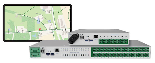
Interested in learning more about remote fiber test systems and how they work? Intended for those seeking a better understanding of solutions for successfully maintaining fiber optic networks, this article focuses on remote fiber testing systems, which are a valuable tool for network operations teams.
Topics: fiber optic testing, otdr, fiber monitoring
Topics: fiber optic training, network simulation
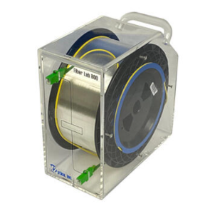
Fiber optic testing and training are important aspects of ensuring optical communications networks operate successfully as designed and intended. When thinking about the big picture, testing and training happen at many different levels and in a variety of instances both before, during, and after the network has been installed.
Topics: fiber optic training

When rolling out and maintaining a fiber optic communications system, latency is a critical factor that must be addressed. Dealing with latency issues can be very frustrating when they occur.
Topics: optical fiber, latency
The act of joining two individual lengths of optical fiber to create a secure connection is called splicing. There are currently two common splicing methods that can be utilized - fusion splicing and mechanical splicing. While both processes share similar initial steps, the differ substantially thereafter in terms of the approach and necessary materials, while producing different results.
With this being the case, how might one choose which path to take? Is one method considered better than the other? In this brief article, we take a closer look at both the fusion and mechanical splicing methods to provide some clarity on the subject. At the conclusion, you should have better idea about how each method works, the benefits and drawbacks of each, and which uses cases or applications are more suited to one or the other.
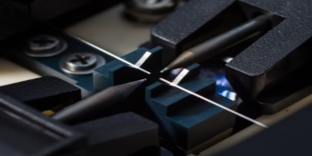
Figure 1: Fusion Splicer machine close-up
Defining Mechanical & Fusion Splicing
The ultimate goal of cable splicing is to create a secure connection between two or more sections of fiber in a way that allows the optical signal to pass through with minimal loss. As we mentioned already, both mechanical and fusion splicing achieve this goal, but they do so in very different ways.
Fusion Splicing
Fusion splicing involves heating the ends of each fiber that are being joined and fusing them together permanently. Because this process requires near-perfect alignment of the fibers and their respective cores, along with fusing the glass together in a precise manner, this is accomplished using a fusion splicer device. The device effectively aligns the two fiber ends, melts the glass via an electric arc, then fuses them together. Because of the resulting splice point in the length of fiber, either a heat-shrinkable protective splice sleeve or a coating material is typically placed over the splice point to give the splice more strength and durability.
Mechanical Splicing
The primary way that mechanical splicing differs from fusion splicing is that it is a manual process that does not permanently fuse or join the fibers together, instead it locks and aligns the fiber ends together with a screw mechanism in a splice case. This method requires no heat or electricity and is performed manually by a technician using the required tools and components.
Fusion Splicing Steps - A Quick Overview
For both fusion and mechanical splicing techniques, there are four distinct steps to the process. The first two steps for each are virtually identical which are covered in this section, but the final two are where the differences come into play.
Fusion Splicing and Mechanical Splicing Step 1 - Fiber / Cable Preparation
To prepare the end of a fiber cable for splicing, a few inches of the protective jacketing, buffer tubing, and coating must be stripped away in order to access the bare glass fiber. After using a handheld stripping tool to remove these layers, the bare fiber is now accessible, which should then be cleaned quickly with an alcoholic wipe to remove any dirt or dust.
Fusion Splicing and Mechanical Splicing Step 2 - Cleaving
Once the bare fiber is prepared, the next step involves cleaving the end fiber, which shouldn’t be confused with cutting. Cleaving is when the fiber is lightly scored with a sharp blade and then flexed until it naturally breaks. To create an ideal connection point for a fusion or a mechanical splice, a clean and smooth cleave that is perpendicular to the fiber is absolutely necessary. The example image below shows examples of poor cleaves on the left and good cleaves on the right:
Topics: optical fiber, mechanical splice, fusion splice

 Headquarters
5621 Departure Dr, Ste 117
Raleigh, NC 27616, USA
 Call Us
Phone: 1-919-342-5619
Toll Free: 866-269-2902
 Email Us