
Latency is a critical performance factor in communications networks as it is the time it takes for data to travel from one point to another. As one might expect, service providers commit a great deal of time and effort attempting to reduce latency across the entire network, to deliver data and content faster to consumers and businesses. While important in general, some applications like financial trading, streaming video, and defense/military communications prioritize latency reduction with the goal of achieving as close to real-time communications as possible.
There are numerous elements and factors in any fiber optic network that impact latency and timing parameters. Differences in optical fiber types, span lengths, network devices, and components all can add and/or change latency values, creating critical timing and synchronization issues at various points across the network. To solve these challenges and optimize performance, engineering teams utilize optical time delays, which are precision-length coils or spools of optical fiber that allow for the necessary adjustments and fine-tuning of signal timing.
Note: While both passive optical time delays and active (electronically-controlled) optical time delay systems exist, this article focuses on passive delay solutions.
Test Lab and Live Network Applications
To solve and optimize signal timing performance, optical time delays are often used in two primary areas:
- The test lab, for accurately simulating the span or link latency of a field network. Replicating fiber span or link latency in the lab is beneficial when designing fiber routes, certifying devices, adjusting performance settings, running transmission scenarios, and attempting to identify and solve potential timing and synchronization issues prior to deployment.
- The live network, for addressing and fine-tuning signal timing, synchronization, and equalization challenges. Examples of network locations where time delays are used include inside data centers, central offices, or remote hubs or nodes. It’s also important to note that fiber delays are not always deployed as a stand-alone solution, they can be built for installation inside of other devices and systems which we will cover later in the article.
Optical Time Delay / Delay Line Solutions for Any Use Case
Specializing in designing and manufacturing advanced optical fiber solutions for latency-driven applications that demand a high degree of fiber length and timing precision, M2 Optics offers a complete portfolio of optical time delays in multiple formats offering maximum efficiency for easier user installation and management.
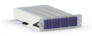
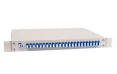
Rack-mount Time Delays / Delay Lines
For test lab or data center applications with several fibers to larger fiber counts, rack-mount Fiber Lab solutions provide the most efficient approach for deploying and using optical time delays. Physical space is usually an important consideration in test labs and a critical consideration in data centers, so rack enclosures housing multiple time delays maximize value while offering the highest density in the least amount of space. Additionally, some rack-mount styles are designed in a modular format, combining space savings with versatility, since users can add or re-configure fiber delay modules as needed to match their new or changing timing needs.
Some examples of customizable, popular rack-mount Fiber Lab solutions include:
 |
|
 |
|
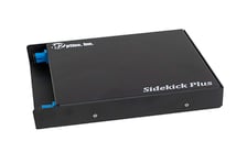
Portable and Modular Time Delays / Delay Lines
Primarily used for test lab and demonstration applications on the bench or tabletop, portable Fiber Lab solutions combine the benefits of fiber delay protection and consistently accurate results with the ability to easily move them around to new locations.
For those seeking or needing shorter delays, modular delay lines offer an even more compact portable enclosure format. It should also be noted that modular delays also work well for easier installation/integration into other devices or systems when added fiber protection is beneficial or manipulating the fiber is not required.
A few examples of customizable, popular portable solutions include:
 |
|
 |
|
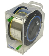
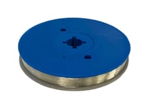
Coil and Spool Time Delays / Delay Lines (No enclosure/housing)
When optical time delays are needed for installation into other devices or systems and the fiber must be accessible for integration purposes (ex: an in-line fiber delay that must be spliced into a fiber path), M2 Optics offers bare fiber coil delays with or without a spool. Coil delays with no spool can be supplied to meet user-specified diameters and dimensions, while for those requiring a spool, M2 manufactures custom-fabricated spools to user specifications.
Specify Your Time Delay Solution - M2 Builds It
To learn more or begin designing a customized solution for your latency-driven application, contact M2 Optics today. Our team of fiber experts will personally help you determine the ideal solution that matches your engineering requirements and objectives.
All Fiber Lab solutions are 100% designed and manufactured at M2's facility in Raleigh NC, USA.


