
While the adoption and deployment of 100G systems and related devices in data centers has continued to grow at a solid pace the past few years, network equipment manufacturers have started taking the next step for supporting even greater bandwidth demands by developing 400G optics and transmission systems.
Similar to the way in which various technology approaches were designed to achieve 100G (ex: 10x10G, 4x25G, etc) via multiple transmit/receive formats using either multi-fiber MPO connections or duplex LC connections (depending on the application), the same has occurred for 400G as well. Thus, when designing, testing, or deploying 400G optics, engineers must have a way to effectively simulate the real-world links in order to achieve the most accurate performance results.
Determining Fiber Types and Distances of the Links
When simulating any fiber optic link in a test environment, the proven best practice is to utilize lengths of the same optical fiber that will be deployed in the actual network, as this is the only way to exactly replicate all of the key performance characteristics. Due to the differences in various fiber types as well as slight differences in performance specifications between fiber manufacturers, matching the fiber type as closely as possible will yield the most accurate results.
Aside from fiber type, the lengths of fiber used are also important when simulating the link. Fortunately, industry standards are developed that specify not only the fiber type, but also the distances associated with the different 400G optics and applications.
Below are just a few examples of some 400G optics industry specifications, which define the maximum transmission distance, the number and type of fibers, and the connection interface:
400GBase-LR8; QSFP-DD Optical Transceiver: 8x50G, 10km SMF, duplex LC interface
400GBase-FR8; QSFP-DD Optical Transceiver: 8x50G, 2km SMF, duplex LC interface
400GBase-SR8; QSFP-DD Optical Transceivers: 8x50G, 100m OM4 MMF, MPO interface
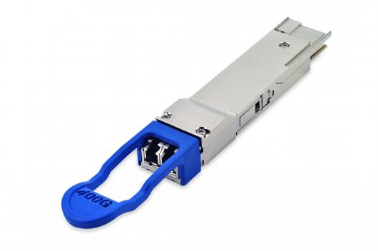 |
Finisar® 400GBASE-LR8 QSFP-DD Optical Transceiver (View). 10km, 8x50GLAN-WDM transmitter, duplex LC interface Image Credit: Finisar Inc. |
Using the known information and industry standards, an engineer designing, testing, or deploying these optics and systems now has the information necessary to simulate the respective links.
Hardware Setup Configurations and Options
Once determining the specific needs in terms of the necessary optical fiber type(s) and length(s), the next step is to choose a great solution that fits into the testing environment accordingly.
To address the different testing objectives engineers have in the lab, partnering with an established network simulation solution vendor like M2 Optics allows for a variety of setup configurations to choose from, along with the necessary customization for achieving your goals. Do you prefer a rack-mount or portable solution? What is the most space-efficient setup available? What degree of accuracy do you require in terms of length or delay values?
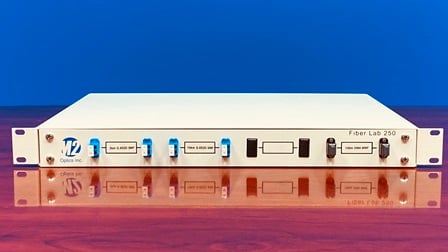 |
Fiber Lab 250 with three complete 400G links: - FR8 (2km, LC) - LR8 (10km, LC) - SR8 (100m, MPO) |
All of these are important considerations when thinking about your 400G setup configuration, but working with a proven partner like M2 Optics will help you to determine a setup that delivers maximum value in line with your testing objectives.
The Future is Now for Simulating 400G Networks / Links
Although the deployment of 400G systems will take time similar to previous 10G and 100G types, the good news for communications engineering teams is that efficient solutions for simulating the related physical links in the test lab are already available. Whether you are a network equipment manufacturer needing to simulate a number of different links for certifying multiple 400G device formats, or you are a network engineer specifying optics and seeking to qualify the best vendor during the pre-deployment phase, a customized setup from M2 Optics can be built to match your exact application requirements and test environment needs.
Learn More!
Contact M2 Optics today for more information about simulating 400G fiber optic links or to begin designing your own customized solution.


