
An important factor in the performance of fiber optic communications systems, chromatic dispersion is a topic and performance characteristic that is important to both understand and account for when operating and/or designing equipment for fiber-based networks.
What is Chromatic Dispersion in Fiber Optics?
When shining a beam of white light into a prism, you see the light is composed of a rainbow band or light spectrum. This phenomenon is an example of chromatic dispersion. Red light with a wavelength of 700nm and violet with a wavelength of 400nm are at the two ends of the visible spectrum. But what causes the light with different wavelengths to separate from each other?
It's the glass!
Whether it is a prism made of glass, or an optical fiber with a fused silica glass core, they both have the ability to bend light with different wavelengths to different angles because glass is a type of dispersive media.
To characterize glass or other types of media that light can travel, a parameter is used called refractive index (or also index of refraction). This number refers to the speed at which light propagates through a medium. The typical index of refraction for a single mode optical fiber is around 1.461, meaning that light travels 1.46 times faster in a vacuum than it does in a fiber. However, this value varies slightly at different wavelengths. Typically in optics, the longer the wavelength, the lower the refractive index (see Fig. 1 below).
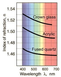
Figure 1: Refractive Index vs. Wavelength2
The definition of the velocity of light is: velocity = speed of light / refractive index
As a result, with different colors of the light spectrum travelling at different speeds due to the differences in refractive index, in the figure above red light travels faster than blue, due to its lower index. Over distance, red and blue will be further separated, thus the signal will be broadened:
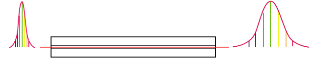
Figure 2: Pulse Broadening Effect3
Over longer distances, this small "dispersion" eventually adds up to a degree that the receiving end cannot properly distinguish between two consecutive signals as the pulses start to overlap:
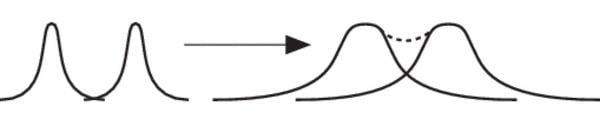
Figure 3: Overlapped Signals4
If not managed, this can cause serious trouble in network communication systems, especially in fast bit rate applications. A 40G system is more susceptible to chromatic dispersion than 10G system because the signal pulses are more densely packed at the source. While a 10G system can go up to one hundred kilometers without trouble, a 40G system can go no further than a few kilometers without the requirement for dispersion compensating solutions.
(Author's comment: It should be noted that specifications for optical fibers often state a group refractive index value, which is based on group velocity, not phase velocity. As a result, the refractive index value increases as the wavelength increases. An example of this can be seen with Corning® SMF-28® Ultra single mode optical fiber, where the RFI @ 1310nm is 1.4676 and @ 1550nm is 1.4682)
How a Dispersion Compensating Module Reduces Chromatic Dispersion
A dispersion compensating module (or DCM) is used to compensate the cumulative dispersion in a single mode fiber and a dispersion coefficient is used to characterize the dispersion value. The value for regular SMF is around +16~17 ps/(nm*km) at 1550nm. To properly manage this, the DCM is built using a special type of dispersion compensating fiber inside the module that has a negative value of dispersion coefficient, ranging from -30 to -300 ps/(nm*km).
As an example, the cumulative dispersion for a 10km length of fiber will be +160~170 ps/nm, so to compensate for that amount of dispersion, a DCM will be added to the link with a specific and calculated fiber length aimed at reducing the total dispersion close to 0 ps/(nm*km).
Want to Learn More?

Since 2001, M2 Optics has been manufacturing DCMs to support network operators requiring compensation for ITU G.652 single mode fibers. Our experienced team of engineers is available to answer any questions you may have on this topic, or help you to design a customized solution for your specific requirements.
Article References:
1. https://www.rp-photonics.com/fibers.html
2. http://hyperphysics.phy-astr.gsu.edu/hbase/geoopt/dispersion.html
3. http://www.thefoa.org/tech/ref/testing/test/CD_PMD.html
4. https://www.newport.com/t/fiber-optic-basics


